

What is a sprinkler?
A sprinkler is a network of pipes that passes through the roof of a building and keeps water under pressure. Each sprinkler is nothing more than a faucet and a hole in the pipe through which water can flow into the underlying building of the system.
In a regular faucet, you turn a screw to open a valve that lets water out.
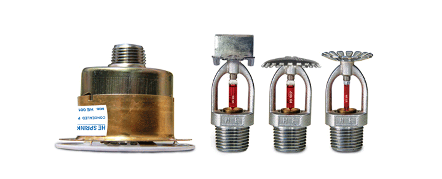
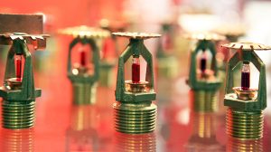
A sprinkler works like a manual faucet, except it’s replaced by a heat-sensitive plug designed to open automatically in the event of a fire. In some sprinklers, the plug is made of an alloy called metalwood, which is a mixture of bismuth, lead, tin, and cadmium and melts at a relatively low temperature. But in other sprinklers, the plug is a small glass bulb filled with a glycerin-based liquid designed to heat up and expand, causing it to break.
The basic idea is the same in both cases: the purpose of the two branches is to break as soon as the fire starts and the sprinkler opens.
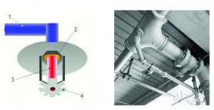
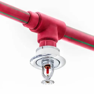
Below is a network of water pipes and key parts of a typical fire sprinkler:
In part (1), water is under pressure in the tube, which is held in place by a small branch (2), and the small branch is also held in place by a glass bulb filled with glycerin (3).
During a fire, the bulb breaks, releases the branch, and allows water to hit the flower-shaped fender, spraying the water around.
Now consider the following figure:
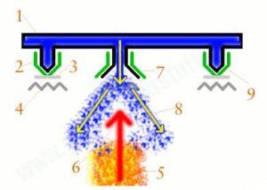
But the metal version of wood works a little differently. The sprinkler is fed by water pipes in the roof (1). Each sprinkler has two spring-like metal arms (2) held together by a wood-metal ring (3). When the metal and wood are intact, the spring arms lock together and close the water pipe so that no water escapes. Directly below each sprinkler is a flower-shaped piece of metal called a deflector (4), but at this point it does nothing useful.
If a fire occurs under the sprinkler (5), the hot gases will circulate upwards towards the ceiling (6). When the temperature reaches about 70°C (160°F), the wood metal melts, causing two spring-like metal arms to open (7). Water can now flow out of the pipe. Water flows down from the pipe in the roof, hits the flower-shaped fender directly, and falls to the ground with a gentle spray in hopes of extinguishing the fire (8). If the fire is small, only the sprinkler above the fire will extinguish the fire and prevent further damage (9). However, if the fire spreads, the surrounding sprinklers will soon be activated until the fire is extinguished or firefighters arrive to help extinguish the fire. Based on the consistency of water distribution, home sprinklers can put out small fires in less than 90 seconds using less than one-tenth of the water of a fire hose.
Types of fire sprinklers
In the first picture above, you can see the blue sprinkler pipes all filled with cold (blue) water. With a fire and the opening of the sprinkler, the water can go out immediately, but in this sprinkler model, if the building is not heated or the weather is cold, the pipes freeze and burst. This system is called a water pipe system, which means that all the pipes in the roof contain cold, pressurized water, ready to release it the moment the metal melts. They respond very quickly and effectively, extinguishing the flames and helping to reduce the effects of smoke and toxic gases from the fire, however, not all sprinklers work this way.
In the second figure, in a dry pipe sprinkler, the roof pipes are filled with compressed air or nitrogen gas (yellow). During a fire, pressurized air is released from the sprinkler, causing a sudden pressure drop in the pipe, and the clapper valve (red) opens, allowing water (blue) to flow along the same pipe to extinguish the fire. . Such systems are used in cold buildings (usually uninhabited and unheated) where water may freeze inside the pipes or the pipes may burst, resulting in flooding and destruction. The disadvantage of this model is that it takes more time for the dry pipe system to activate – literally, every second counts when there is a fire – so sprinklers like this are only used when absolutely necessary. While it is possible to install a dry pipe system in a very cold building, it is imperative that the valve that opens through air pressure to release water be protected from freezing by some form of steam.
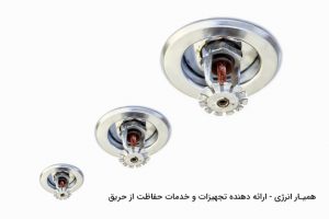
Automatic sprinklers may look the same to everyone at a glance, but there are different types that are designed to respond to different temperatures and speeds and work in different types of buildings and environments. They can be placed traditionally, on a downward sloping ceiling, in an upward storage space; or on a side wall that points inwards. Some have special coatings (such as Teflon or polyester) to protect them in corrosive environments or other challenges. They are also available in a wide range of designs and colors. For example, residential sprinklers often have a neat design with a cover cap, so they are partially or completely recessed into the ceiling or wall.
What does the sprinkler system look like from the outside?
Apart from the automatic sprinklers, there is a network of pipes in the roof, inspection valves for testing (so the system can be checked periodically), a drain connection (to drain the pipes for routine maintenance) and a connection Fire department (also called FDC or Siamese connection) – A standard connection to which the fire department can connect a hose and pump additional water into the sprinkler system if necessary, usually in a highly accessible location in It is located outside the building or in a nearby parking lot.
Who invented the sprinkler?
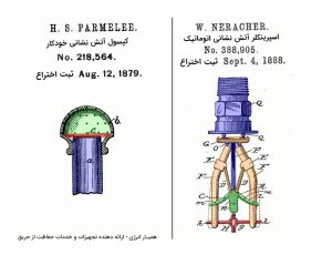
Modern-style sprinklers like the one described above, based on an alloy that melts in a fire, were invented in the 1870s by Henry S. Parmelee of New Haven. If you check the records at the United States Patent and Trademark Office, you’ll find that Parmelee has several patents for sprinklers (or “automatic fire extinguishers,” as he calls them) on his resume, including a very The simple one shown on the left is a photo of a metal cap with a fusible solder on the end of the tube, designed for critical situations during a fire.
The artwork on the right is a more modern looking sprinkler designed by William Naracher about a decade later. You can clearly see the spring arms and the branch that keeps the water pipe closed. More than a century later, modern sprinklers still work the same way. In fact, good ideas never go out of style!
Ways to prevent sprinkler freezing in the building
Some businesses worry about their sprinklers freezing during certain seasons of the year due to falling temperatures and snowfall. In fact, there is a risk of freezing in the cold winter months, such as the inlet pipes to the sink. In the event of a commercial fire, frozen sprinklers will not help building occupants, so it is imperative that building owners take proper precautions to prevent sprinklers from freezing. Here are some tips on how to prevent sprinklers from freezing in a commercial building.
Types of sprinkler system are divided into two general categories: wet system or dry system. There is a possibility of freezing in the sprinkler system. Adequate heating should be used throughout the building to prevent pipes and sprinklers from freezing. If the building only uses small wall heaters as a heat source, not enough heat can reach the pipes.
Your home or facility needs a reliable heating system to replace the heat outside the building. One of the most common causes of sprinkler system freezing is when the heat in the building is accidentally turned off or the power goes out. Areas with the greatest risk of freezing are entrances, stairways, attics, skylights, and basements.
According to the NFPA standard, in areas where there is a possibility of the fire extinguishing system freezing, the anti-freezing system should be used. Also, the antifreeze solution can be Glycerine or Propylene Glycol, and considering that these two substances are flammable, they should be mixed with water in a composition with a precise percentage and injected into the system to prevent freezing of the extinguishing system. The maximum volume concentration of glycerin in solution is 48% and propylene glycol in solution is 38%. It should be noted that any increase in concentration compared to the stated values in the presence of a heat source leads to the ignition of the antifreeze solution and the spread of the fire.
Due to the danger of carbon monoxide, never use fuel-burning heaters to prevent the sprinkler from freezing. Instead, simply increase the temperature of your HVAC system (Heating, Ventilation, and Air Conditioning) to ensure that there is enough heat to prevent freezing. The damage has been transferred.
Inspect your building to see if there are any gaps in your insulation or foundation. These cracks can reach your pipes and sprinkler system and cause freezing.
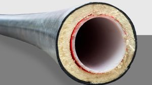
Properly installed mineral fiber insulation is the most practical solution to reducing sprinkler pipe freezing. The property of this insulation to slow down the flow of heat is expressed by the value of R. The higher the R value of the insulation, the greater its ability to prevent heat loss. High R-value insulation is installed between the pipe and the outside space. This is especially important in areas that go below 40 degrees Fahrenheit.
Another strategy to reduce the chance of frozen pipes is to use “heat tracing,” which uses a flexible, electric heating unit that wraps around the pipe to provide heat when needed.
If you find that your sprinklers are frozen, never use an open flame to melt them. An open flame can not only damage sprinklers, but also lead to commercial fires.
Before the winter months, it is recommended that you consult a sprinkler specialist for an annual inspection, which may include flushing the sprinkler system. After flushing the system with water, the pipes are dried by blowing air pressure into them.
Ideally, all sprinkler systems should be properly designed and installed to suit their environment. Regardless of what system you use, freezing of fire protection systems can be controlled.
At Hamiyar Energy Company, we offer a range of portable fire extinguishers and fire alarm systems to secure commercial buildings. Hamyar Energy offers the highest quality alarm systems to protect your business from fire and carbon monoxide poisoning. We also offer fire suppression systems to help control commercial fires in the event of a fire. Our trained consultants will guide you in determining which smoke detection system is best for your business.
Pump installation in sprinkler systems
From the middle of the 20th century, the installation of “centrifugal” or centrifugal pumps in fire extinguishing systems became popular. The use of this equipment increased day by day due to the following reasons and events:
The demand for installing sprinkler systems has increased day by day.
In 1990, NFPA increased the minimum pressure required for Class I fire hose water mains from 65 psi to 100 psi. In most cases, municipal water mains were capable of providing 65 psi water pressure, but providing 100 psi pressure required the installation of a pump. is.
Increasing the use of ESFR sprinklers, which requires the installation of a pump on the system to reach the minimum working pressure required for these types of sprinklers.
Installing sprinkler systems in buildings far from the city where there are no city water sources.
But what is the function of the pump in the fire fighting system? Pumps increase the inlet water pressure by a certain amount, but cannot change the inlet flow rate. Therefore, if it is determined after the tests related to measuring the flow rate and pressure of urban water (such as the Pitot test) that the flow rate of the city water network is lower than the required flow rate of the system, using a pump alone will not help (in this case, the sources help such as water tanks should be used), but if the urban water network provides the minimum flow required by the system, a pump can be used to increase the pressure to the required amount of the system.
To clarify the issue, pay attention to the graph (1) in which the results of the urban water source analysis are displayed. This source provides a static pressure of 75 psi and a residual pressure equal to 25 psi at a flow rate of 800 gpm. If we continue the curve, it cuts the horizontal axis at the point of 989 gpm.
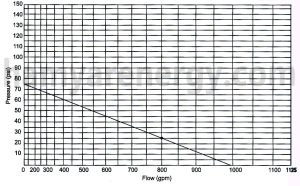
Chart 1-Analysis of Pitot test results on city water
If we install a pump with a rate of 750 gpm and 60 psi on the network, the curve will change as shown in diagram (2). That is, at a flow rate of 750 gpm, the pressure will increase to 90 psi (90=60).
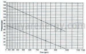
Diagram 2- Pump installation with a rate of 60 psi, 750 gpm
Pay attention to two points in this regard:
1) This pump produces about 65 psi at no flow or 0 gpm, 60 psi at 750 gpm flow rate and 55 psi at 989 gpm flow rate, which can be justified considering the pumps curve, according to Curves of pumps As the flow rate increases, the net pressure produced by the pump decreases.
2) In Figure 2, the curve was continued up to a flow rate of 989 gpm, because the city water source cannot provide a higher flow rate. But in most urban water systems, the pressure of the network should not fall below 20 psi, therefore according to the diagram (3), the maximum allowable flow rate will be equal to 837 gpm.
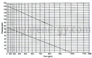
Diagram 3- The maximum allowable flow rate of the pump
Providing pressure in sprinkler systems
When the tank is used in the fire extinguishing system, the supply of pressure in the system is done by a pump, gravity or compressed air (in pressure tanks). Fire pumps are used in sprinkler systems, fire hose networks, water mist systems, and foam systems.
Except Jockey Pumps, other pumps used in Fire Pumps must be listed. (The jockey pump is installed to compensate for small pressure drops in the system to prevent the main pumps from turning on)
In this section, explanations are given about fire pumps, but before that, in order to get more familiar with the operation of the pumps, we will define suction pressure, discharge pressure and net pressure of the pump:
Suction Pressure:
The water pressure at the moment of entering the pump must be a positive value (that is, more than atmospheric pressure). If this value is negative, the pump performance is impaired and the suction pipe of the pump may be crushed and deformed.
Discharge Pressure:
The water pressure is at the moment of leaving the pump. It should be noted that the working pressure of the equipment installed after the pump is higher than the pressure of the water.
Net Pressure:
The pressure produced by the pump is equal to the difference between suction pressure and discharge pressure. Pumps produce a certain net pressure and are independent of the water pressure entering the pump, for example, suppose the pump net pressure is 45 psi in a flow of 500 gpm, if the suction pressure is 20 psi, the discharge pressure is 65 psi, and if the suction pressure is 100 psi, the pressure will be 145 psi (of course at 500 gpm flow).
PN = PD – PS
PN: net pressure
PD: pressure
PS: Suction pressure
The pressure produced by the pumps is proportional to the speed of the pump, the higher the speed of the pump, the more water it pumps at a higher pressure. The following formulas express the relationship between pressure, flow and pump speed:
N2: Pump circulation speed in secondary mode
N1: Pump circulation speed in the initial state
Q2: flow through the pump at the secondary circulation speed Q2=Q1 (N2/N1)
Q1: flow through the pump at the initial circulation speed PN2=PN1|(N2/N1)
PN2: Net pressure produced by the pump at secondary circulation speed
PN1: net pressure produced by the pump at initial circulation speed
It is possible to use water tanks in sprinkler systems under the following conditions:
1- When the urban water network is not available or does not have the ability to provide the required flow rate and pressure of the fire extinguishing system, the best solution is to use water tanks in sprinkler systems.
Unfortunately, some building owners are deprived of having fire extinguishing systems due to the lack of proper city water network. If using water tanks in sprinkler systems, they can extinguish the fire in moments or with very small amounts of water. For example, for a sprinkler system designed in a low-risk environment, about 120 gallons per minute of water will be consumed in 30 minutes, which means that the fire can be easily extinguished by choosing a 3600-gallon tank. If the output of each fire hose is about 250 gallons per minute, suppose that due to the lack of a sprinkler system and the fire brigade’s arrival time, the fire spreads and the firefighters use 4 hoses at the same time. In this situation and during 30 minutes, about 30,000 gallons of water will be used, which in addition to increasing the negative effects, more than 8 times the required amount of sprinkler system, water is consumed.
2- Buildings are divided into several fire zones or zones.
The problem we face in most high-rise buildings is that in order to ensure the minimum pressure required at the farthest sprinkler or fire hose outlet, the water pressure at points closer to the pump exceeds the permissible limit (175 psi), in this condition Dividing the network into two or more zones is necessary for using water tanks in sprinkler systems. Pay attention to the following example (in this example, only the effect of height on pressure is considered and the pressure drop due to friction is ignored.)
Consider a 700-foot-tall building that uses a riser to supply water to the outlet hoses on each floor, if we want a residual pressure of 100 psi (Residual Pressure) at the outlet in accordance with NFPA 14. If we provide a 2½” diameter at the top floor, the pressure at the ground floor will be about 403 psi. (Figure 1)
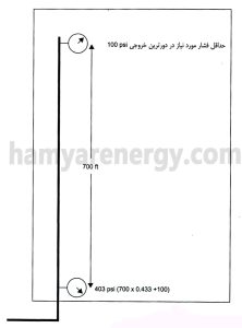
Figure 1-Increasing the pressure to more than the permissible limit in each ground floor
The pressure of 403 psi is higher than the working pressure of equipment used in fire extinguishing systems. However, if the building is divided into two zones (Figure 2) and the water tank and pump are used at a height of 340 feet, the additional pressure near the pump can be reduced. Using this method, the pressure at the outlet of the ground floor will be around 247 psi in the lower zone and around 252 psi in the upper zone. Although these two pressures are higher than the standard limit (175 psi), but with the help of pressure regulating valves, they can be reduced to 175 psi. (For every foot of elevation change, the pressure changes by 0.433 psi, if the number of zones increases, the fluid pressure near the pumps will be lower and there will be no need for pressure reducing or regulating valves.
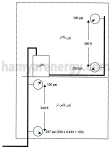
Figure 2 – Dividing the building into two zones (pumps are not shown in the picture)
3- To ensure the water supply of the system
In order to ensure the system’s water supply, two sources are sometimes used in fire extinguishing systems, although NFPA and other building codes consider one water source to be sufficient, but some insurance companies in the United States offer significant discounts for the system. They have two sources of water.
4- Installing the system in earthquake-prone areas
In earthquake-prone areas where there is a possibility of urban water pipes breaking due to an earthquake, the use of water tanks in sprinkler systems is necessary when necessary, so that in case of interruption or reduction of water pressure and flow in the urban network, it is possible to use the water tank Exclusively, he used the sprinkler system.
Municipal water sources in sprinkler systems
Before choosing urban water sources, the pressure and flow of the water network must be ensured, it is assumed that these sources have the ability to provide water in a certain period of time, but the values of flow and pressure must be calculated by conducting tests. In addition to the water supply of the sprinkler system, they should also provide the water needed for the water network of the fire hoses so that the firefighters can extinguish the fire using the fire hoses.
Before performing the tests related to determining the characteristics of the water source, safety points regarding the direction of the water coming out of the hydrant, the effect of the output water pressure on the equipment in the area, and the use of personal safety equipment such as goggles should be observed.
One of the methods of testing the urban water source is the use of “Pitot Gauge” (Figure 1), with the help of this device, the velocity pressure of the water coming out of the hydrant can be measured and using the following formula or Table 1 Calculate the flow rate.
Q=29.83 cd2(Pp)1/2
that in the above relationships:
Q: Output flow rate from the hydrant (gallons per minute)
C: hydrant coefficient (depending on the type of hydrant, it is 0.7, 0.8 or 0.9. (Figure 2)
d: hydrant outlet inner diameter
Pp: Velocity pressure of the fluid which is read from “Pito manometer”.
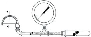
Figure 1- “Pito pressure gauge”
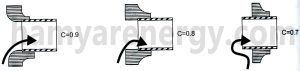
Figure 2- The larger the coefficient c is, the smoother the water exit path is.
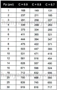
Table 1- Calculation of flow rate through pitot test
The testing time should be during the hours when the city network is at its maximum consumption so that the lowest pressure and flow rate provided by the network can be estimated. In order to be sure about this matter, the relevant officials should be consulted.
In the pitot test, we consider that there are two hydrants in the vicinity of the sprinkler system installation location (Figure 3). On the first hydrant (standard hydrant), which is closer to the main water pipe, we install the pressure gauge (Figure 4) and read the static pressure of the water network. After measuring the diameter of the outlet of the second hydrant (flow hydrant), open its valve. and we measure the velocity pressure of the fluid through Pitot (Figure 5). While the valve of the second hydrant is open, we note the amount of residual pressure through the pressure gauge on the first valve. We close the valves very slowly, observing safety precautions.
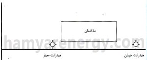
Figure 3- The arrangement of hydrants relative to the main water pipe
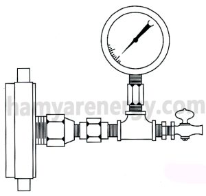
Figure 4- The pressure gauge that is installed on the standard hydrant
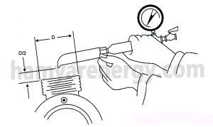
Figure 5 – How to take pitot pressure gauge against the flow hydrant output
Opening and closing hydrants should be done slowly to avoid water hammer.
In the impact of the ram, when the flow waves inside the pipe collide, the energy of the waves accumulates together and leaves destructive effects on the piping and installed equipment.
After performing the pitot test, we evaluate the obtained information to check the possibility of using the city water network as a water source for the sprinkler system.
The easiest way to evaluate information is to draw a graph, due to the non-linearity of the relationship between flow and pressure, common graphs cannot be used, but for this test, special graphs called log 1.85 have been designed, the horizontal axis of the graph, the flow in gpm and the axis Vertical specifies the system pressure in psi. (Chart 1)
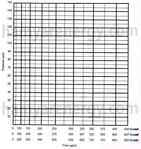
Chart 1- log 1.85
To learn more about the pitot test information evaluation method and log 1.85 graph, pay attention to the following example:
Example) Given the following data from a pitot experiment, plot log 1.85 with respect to this source.
Static pressure: 80 psi
Residual pressure: 47 psi
Speed pressure: 14 psi
Hydrant coefficient: 0.9
Inner diameter of hydrant outlet: 2.5
Before drawing the graph, we obtain the flow rate based on the velocity pressure:
Q=29.83 cd2(Pp)1/2 = (29.83)(0.9)(2.5)2(14)1/2 = 627 gpm
First, on the log 1.85 graph, we determine the static pressure of the system, that is, when the second hydrant valve is closed and the flow is zero.
The second point on the graph is when the second hydrant valve is opened and the remaining pressure is 47 psi and the flow rate is 627.5 gpm (to simplify the drawing, we consider the flow rate to be 630 gpm)
The line connecting the two marked points on the graph is the system water supply curve. Based on this curve shown in Figure 2, the flow rate will be 400 gpm at a pressure of 66 psi and 750 gpm at a pressure of 35 psi.
In most urban water systems, the pressure of the system should not drop below 20 psi, that’s why the curve is slightly extended to determine its intersection with the pressure of 20 psi, this point is the maximum flow that can be provided by the urban water network.
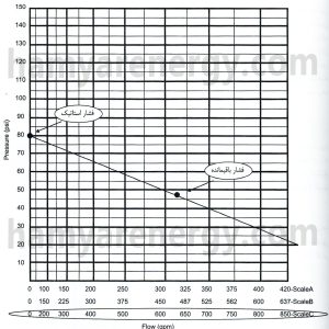
Diagram 2- log 1.85 regarding the above example
Water sources in sprinkler fire extinguishing systems
A fire sprinkler system is an active method of fire protection that consists of a water supply system that supplies sufficient pressure to the water distribution piping system to which the fire sprinklers are connected. Although historically only used in factories and large commercial buildings, these systems are now available in homes and small buildings at affordable prices. Fire sprinkler systems are widely used around the world and more than 40 million sprinklers are used annually. Even though fire sprinkler systems are a life-saving system and not designed to protect the building, 96% of buildings that have had a fire are saved from complete fire by sprinklers. Now, providing water with sufficient flow and pressure in a certain period of time is one of the most important issues in the design of sprinkler systems. Without proper water sources in sprinkler fire extinguishing systems, even the most well-equipped and trained firefighters or the best and most accurate sprinkler systems cannot control the fire.
First, we define three quantities that are widely used in supplying water sources in sprinkler systems:
Flow: The amount of water that passes through a certain cross-sectional area at a certain time is called flow or discharge, due to the conceptual relationship of this parameter with quantity, it is displayed with the letter Q. The unit of flow in the English system is gallons per minute or cubic feet per minute and in the metric system it is liters per minute, liters per second or cubic meters per minute.
Pressure: is the energy stored in the water that causes it to move within the piping network. Pressure and flow are proportional to each other and an increase in pressure will increase the flow rate. The unit of pressure is psf or psi in the English system and bar or pascal in the metric system.
Duration: Water pressure and flow must be provided for a specific period of time in order to be able to control or extinguish the fire, this duration varies from 7 to 120 minutes depending on the condition of the building.
The most suitable place to install a sprinkler
Improper placement of sprinklers will not only reduce fire extinguishing ability but also cause many problems.
Important points in determining the exact location of sprinklers are:
Even if possible, the sprinkler should be installed near the roof.
The greater the distance of the sprinkler from the ground, the faster the water droplets reach the fire source with the help of gravity.
Installing sprinklers near the ceiling also reduces the risk of damage and physical injury.
Considerations that should be considered in determining the location of sprinkler installation are:
Type of roof structure.
Type of sprinkler selected
The minimum and maximum distance allowed for the installation of sprinklers.
Location of walls and room dividers.
Location from the point of view of fire hazard.
Obstructions in the path of heat caused by fire and water discharged from sprinklers.
Distance or proximity to thermal places.
Types of sprinklers are:
Upper female, female lower, female lateral
Sprayer, ESFR, Large drop
residential or with extensive Exten.Cov coverage
Distance between upper and lower sprinklers
The minimum installation distance between sprinklers is 6 feet.
The maximum sprinkler installation distance in low and normal hazard locations is 15 feet.
The maximum distance to install sprinklers in high-risk places is 12 feet.
The distance between the sprinklers on each branch is indicated by the letter S and the distance between the branches by the letter L.
In cases where the roof slope is more than ten percent, the sprinkler must be installed in such a way that its deflector is parallel to the edge of the roof.
The distance of the first sprinkler from the wall is equal to half of the allowed distance (12 or 15 feet).
The minimum allowed distance of sprinklers from the wall is 4 inches.
If the angle between the walls is not right, the sprinkler installation location will be 7.5 feet on the side walls and 11.5 feet from the corner.
In small rooms, the distance of the sprinkler to one of the walls of the room can be considered to be about 9 feet.
Area covered by each sprinkler
| Maximum coverage area of any sprinkler | System calculation method | Roof structure |
Environment |
| 168 square feet | Both methods | Flammable and blocking | low risk |
| 130 square feet | Both methods | any type | Normal risk |
| 100 square feet | hydraulic | any type | risky |
| 100 square feet | hydraulic | any type | A warehouse with a height of more than 12 feet |
The distance of the sprinkler deflector from the ceiling
- The sprinkler should be installed at the closest distance to the ceiling.
- For ceilings with non-blocking structures, the minimum distance from the ceiling is 1 inch and the maximum distance is 12 inches.
- For roofs with blocking structures, in most cases, sprinklers should be installed at a distance between 1 and 6 inches below the members of the structure, provided that the distance from the roof does not exceed 22 inches.
- On sloping roofs, sprinkler deflectors should be installed parallel to the roof ridge.
- The location of the highest sprinkler should be within 3 feet of the highest point of the roof.
Temperature sensitivity of the sprinkler
In most cases, sprinklers with normal temperature classes are used in the systems, except for the following:
- in a dangerous environment.
- near heat sources.
- In areas where the average ambient temperature is high.
Temperature sensitivity selection table of sprinklers
| Temperature close to the ceiling | Sprinkler temperature |
| 38 C° | 57 ~ 77 |
| 66 C° | 79 ~ 107 |
| 107 C° | 121 ~ 149 |
| 149 C° | 163 ~ 191 |
| 191 C° | 204 ~ 246 |