Hamyar Energy Company produces HE brand sprinkler in Iran
The first sprinkler system in Iran – the national production of Iftikhar Melli

Types of fire sprinklers manufactured by Hamyar Energy Industrial Group and Factories:
Hamiyar Energy Company is the sales representative of German JOB brand sprinkler heating bulbs in Iran
The use of American UL certified heat bulbs in the sprinklers produced by this company


In degrees and types of response to fire:
HE sprinkler in different degrees:
۵۷ °C – 68 °C – 79 °C – 93 °C – 141 °C – 182 °C – 260 °C
۱۳۵°F -155°F -175°F -200°F -286°F -360°F -500°F
The color of bulbs of different degrees in order: orange-red-yellow-green-blue-purple-black
Response type of sprinklers:
Standard answer
quick response
Sprinkler system equipment and components
NFPA 13, in most cases, except for equipment that does not have a major and critical impact on the system (such as drain piping, drain valves, and signs) requires only the use of “Listed Equipment” in systems. Fire extinguishers are allowed, but what is meant by listed equipment?
Simply and briefly:
- Equipment that is included in the lists published by reputable testing companies such as UL and FM.
- Reputable companies and laboratories should inspect the factory producing this equipment permanently.
- Equipments that are made according to valid standards or have passed tests to prove their applicability in fire extinguishing systems.
In this section, we will examine different sprinkler systems and equipment used in each section:
Part I – Water resources
The starting point of all sprinkler systems is the source of water. The source must be automatic so that water can move through the pipes and exit the opened sprinkler.
The sources that can be used in sprinkler systems are:
- Municipal plumbing or site-specific water network
- Water tank and pump
- Pressure Tank
- Elevated Tank
Second part – system pipes
A- Underground pipes:
In most cases, water sources are connected to indoor firefighting systems through underground pipes. The required pipes must be made according to AWWA or ASTM standards.
and have a low pressure tolerance (Working Pressure) equal to 150 PSI. Table 1 shows the standards related to the types of underground pipes from NFPA 13.
| Materials | Standard |
| Cement mortar ester for unbreakable cast iron pipes and fittings, especially for water | AWWA C104 |
| Polyethylene coating for cast iron pipes | AWWA C105 |
| Ductile iron and gray iron fittings from 3 to 48 inches diameter for water and other liquids | AWWA C110 |
| Rubber washers for unbreakable cast iron pipes and fittings | AWWA C111 |
| Flanged ductile iron pipes with rib flanges of gray iron or ductile iron | AWWA C115 |
| Thickness design for unbreakable cast iron pipes | AWWA C150 |
| Unbreakable cast iron pipes, cast or centrifugal method for water | AWWA C151 |
| Special steel pipes for water with a diameter of at least 6 meters | AWWA C200 |
| Tar coating and lining for special water steel pipes | AWWA C203 |
| Cement mortar coating and lining for special water steel pipes | AWWA C205 |
| Steel pipe for water systems from 4 to 144 inches | AWWA C207 |
| Dimensions for the construction of water visa steel pipe connections | AWWA C208 |
| Asbestos cement distribution pipes from 4 to 16 inches diameter for water and other liquids | AWWA C400 |
| Choosing Abstos cement water pipes | AWWA C401 |
| Installation of asbestos cement pipe | AWWA C603 |
| Steel pipes – guidance for design and installation | AWWA M11 |
Table 1 standards related to types of underground pipes
B – Pipes on the ground:
Pipes used on the ground must be manufactured according to recognized standards such as AWWA and ASTM and have a working pressure of 175 psi.
NFPA 13 approved items and standards related to floor piping are listed in Table 2.
| Materials and dimensions | Standard |
| Iron pipes (welded and seamless) | – |
| Specifications of black and galvanized seamless welded steel pipes for fire extinguishing systems | ASTM A795 |
| Specification of welded and seamless steel pipes | ANSI/ASTM A53 |
| Mild steel pipes | ANSI B36.30M |
| Specifications of welded steel pipes resistant to electricity | ASTM B75 |
| Copper tubes (drawn, seamless) | – |
| Specifications of seamless copper pipes | ASTM B75 |
| Specifications of seamless copper pipes for water | ASTM B88 |
| General specifications and conditions for seamless copper and soft copper alloy tubes | ASTM B251 |
| Lubricants for soldering copper and copper alloy pipes | ASTM B813 |
| Soldering metals | ASTM B32 |
| Alloy material | ASTM B446 |
Table 2 standards related to the types of pipes that can be used on the ground
The third part – sprinkler system valves and connections:
In general, the valves used in the sprinkler system are divided into three groups:
۱- Control Valves
Control valves are used to open and close the water inlet to the sprinkler system, and to avoid “water hammer”, these valves should not be closed for less than 5 seconds. In Figure 1, examples of common control valves in fire extinguishing systems are shown.
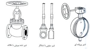
Figure 1 Types of control valves
At least one listed control valve must be installed on each sprinkler system. In cases where there is a common riser for the sprinkler system and the water network of fire hoses (systems not consisting of piping network and connections related to fire hoses used for manual extinguishing) are used), a control valve is installed for each floor so that during the repairs of the sprinkler system, there is no disruption to the operation of the firefighting water network.
The control valves are monitored by electrical or mechanical equipment to inform the relevant personnel if they are closed.
۲- One-way valves (Check Valves):
These valves allow the flow to flow in only one direction. Every system needs a one-way valve to separate sprinklers from the water source, which are often installed on the riser. Since one-way valves are used to separate water sources from other parts of the system. sprinkler is used, if two or more water sources are used in the system, control valves should be used on both sides of the one-way valve so that the repair or testing of the one-way valve does not interfere with the system’s performance.
Figure 3 shows an example of a swing check valve. This type of valve has a very simple mechanism and works with gravity. Unfortunately, a small amount of water moves in the direction of the allowed path. And this issue has caused this milk to be used less in the last few years.
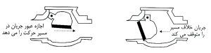
Figure 2 is an example of a hinged one-way valve
Figure 3 shows an example of an “Internally loaded one-way valve”. This type of one-way valve is more used in fire extinguishing systems due to the possibility of a very low error. The spring used in The flow mode without pressure or low pressure causes the water path to be closed. The disadvantages of the one-way valve under internal load compared to the hinged one-way valve are:
- Loss of spring elasticity over time
- The possibility of more failure due to the presence of more components
- The need for higher water pressure to push the spring back
- More pressure drop in the system and impact on hydraulic calculations
- Higher cost
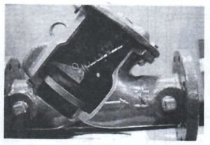
Figure 3 One-way valve under internal load
Two other types of one-way valves approved by NFPA 13 are:
- One-way alarm valve (Alarm Check Valve)
- Backflow Preventer
“Warning one-way valve” is a valve that sends a signal to alert people in the building that the sprinkler system is activated when it opens and water moves towards the sprinkler system. Other types of one-way valves can be called “Preventing “backflow” pointed out.
۳- Test valve and side connections
A- Inspection branch
This branch is installed to test the performance of water flow alarms (Water Flow Alarm) in all wet, dry and pre-operator systems (if compressed air is used). The pipe size of this branch is equal to “1” and the orifice is equivalent to the smallest sprinkler. has a system
The installation location of the inspection branch in wet systems can be anywhere in the system after the flow alarm.
In dry systems, this branch is also known as “Trip Test Connection” and is installed in the vicinity of the farthest sprinkler located on the highest floor. The important point in choosing the installation location of the inspection branch is to pay attention to the possibility of collecting and directing the water coming out of it.
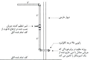
Figure 4 branch of inspection
B – Fire Department Connection:
This branch is used for two purposes in sprinkler systems:
- Supplying the required water for sprinklers in case of problems in the water sources of the system
- Water supply required by the network of fire hoses for the use of firefighters inside the building and fire suppression
Fire Department Connections, abbreviated as FDC, is used as the input of the sprinkler system or the riser network, and during a fire, by connecting to the vehicle of the fire department, it supplies the system with the required water. The installation location of the fire branch must be selected accordingly. that the fire engine can easily access.
The fire department should be equipped with a cover to prevent objects from entering it, and the covers should be easily removed by the personnel of the fire department.
If the sprinkler riser size is 3 inches or less, a “single entry” fire branch can be used.
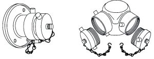
Figure 5 Fire branch equipped with a cover – “double entry” (right) and “single entry” (left)
The type of connection of the fire department is determined according to local laws, in Iran Storz connection is often used.
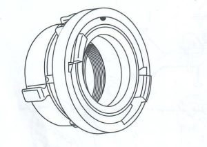
Figure 6 Storz connection
NFPA 13 requires the installation of a fire branch in all sprinkler systems, except for the following conditions:
- The location of the building in far places and outside the coverage of firefighting organizations.
- Flood systems that require water pressure greater than the capacity of the fire truck pump.
- One-story buildings that have an area of less than (186 m2) 2000 ft2, in these small buildings, firefighters have the ability to attack the fire from outside the building.
According to NFPA 13, signs and boards with a font height of one inch should be installed next to the fire branch and information such as the required water pressure of the system should be listed on it.
The one-way valve must be installed on the “fire branch” pipe and before connecting to the sprinkler system pipe in order to prevent the water from the sprinkler system from leaving the “fire branch”. Also, this valve must be installed after the one-way valve of the sprinkler system. To prevent the movement of water pumped by the fire engine towards the source of the system.
The control valve should not be installed on the “fire branch” so that the passage of water to the sprinkler system is always open, and the “fire branch” should not be installed in the suction part of the pump because in this case the inlet water pressure is about 150 psi. From entering the pump, it will reach an excessive pressure that may damage the pipes or other equipment of the system.
The installation location of the “fire branch” pipe to the dry sprinkler system is shown in Figure 7 and pre-operator systems in Figure 8.
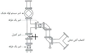
Figure 7 Installing the “fire department branch” pipe to the dry sprinkler system
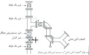
Figure 8 Installing the “fire branch” pipe to the pre-operator sprinkler system
Section IV – Warnings
Water Flow Alarms:
This equipment is used to notify people inside the building of the activation of the sprinkler system, and according to NFPA, it should:
- be listed.
- have the ability to detect a flow equivalent to the output of a sprinkler (with the smallest orifice).
- They will sound within 5 minutes after the start of the flow.
Alarms work in both mechanical and electrical ways. In the mechanical type known as “Water Motor Gong” (Water Motor Gong), the flow of water after hitting and moving small paddle-shaped wheels, causes it to move and sound the alarm. will be
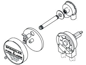
Figure 9 blue engine alarm
In the electric type, the water flow is detected by the pressure switch or paddle type flow switch and completes the electric circuit of the alarm. Examples of equipment used in this system are shown in Figure 11.
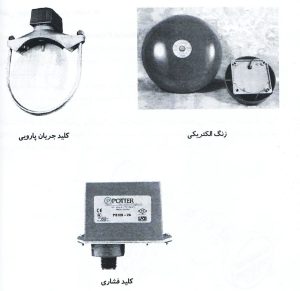
Figure 10 mechanical and electrical alarms
Flow alarms should also be installed in pre-operator and flood systems to notify the passage and movement of water flow independently of the fire alarm system.
In high-rise buildings with a height of more than 23 meters, one control valve, pressure gauge, flow switch and inspection branch should be installed for each floor.
The fifth section – sprinklers:
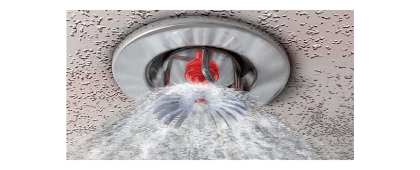
Modern sprinklers can be installed in three ways: top, bottom and wall, all the water coming out of these sprinklers is discharged to the ground.
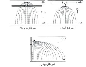
Figure 11. Modern sprinklers discharge 100% of water to the floor of the room.
The old type of sprinklers had holes on the deflector, which caused part of the water (about 40%) to drain towards the ceiling and the rest towards the floor of the room. Due to the discharge towards the ceiling, the coverage area of these sprinklers is less than the It was modern and therefore they were installed closer to each other.
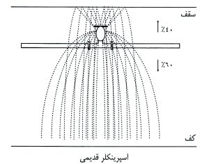
Figure 12. Old sprinklers that discharge 40% of water to the ceiling and 60% to the floor.
Some of the factors affecting the choice of sprinkler installation direction are:
Architectural features, type of roof, type of pipes and fittings used, type of sprinkler system selected, and distance between sprinkler and building equipment.
Choosing a sprinkler in terms of temperature:
Another factor that is considered in the selection of sprinklers is the activation temperature of the sprinkler system. This temperature should be higher than the maximum temperature of the room near the ceiling so that natural factors do not lead to the opening of the sprinklers. At the same time, it should be noted that whatever If the activation temperature of the sprinklers is chosen higher, the reaction speed of the system will decrease.
The color of the liquid inside the bubble of glass sprinklers and the color of the body of thermal connection sprinklers indicate the temperature of the sprinklers.
Using Table 3, derived from NFPA 13, sprinklers can be selected in terms of temperature, for example, if the highest temperature near the ceiling is 150°F (or 66°C), the sprinkler temperature should be between 175 and Choose 225 degrees Fahrenheit, which is in the middle class, the color of the body of the sprinklers of the fast-melting connection is white, and the color of the bubble of the glass sprinklers of this class is yellow or green.
Under normal conditions, in most systems sprinklers of normal temperature class are used.
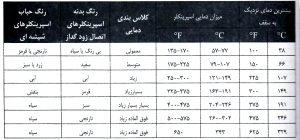
Table 3 sprinkler selection based on the maximum ambient temperature
The distance of installing sprinklers from heat sources:
When installing sprinklers around heat sources, it is necessary to pay attention to the temperature of the ceiling in that range. In Figure 14, taken from NFPA 13, the required temperature class of the sprinkler is specified, if installed near the heat source. For example, sprinklers installed in A distance of 7 feet from the heat source (regardless of the direction of air flow), should be selected from the “high temperature class”. If the sprinkler is installed in the air flow path and at a distance between 7 and 20 feet, “medium temperature class” sprinklers should be used.
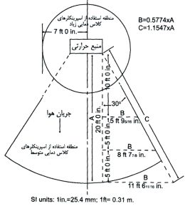
Figure 14: Choosing the temperature class of sprinklers based on the distance from the heat source
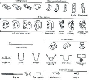
The sixth section – Hanger:
A hanger is used to connect the pipes of the sprinkler system to the building, these equipments must be selected in such a way that they can withstand five times the weight of the pipe full of water plus 250 pounds (114 kg), which is 250 pounds as a safety factor and equivalent It is the approximate weight of the plumber of the system, when it loses its balance and hangs on the pipe. In general, the hangers should be iron in order to be more resistant to the heat caused by the fire. If using other items , must have passed the relevant tests against fire.
Figure 15 shows examples of common fasteners.
Distance between hangers:
The maximum distance between the hangers depends on the type and size of the pipe. In Table 4, the distance between the hangers is determined based on the type and size of the pipe. For example, if the diameter of the copper pipe is 2 inches, the hangers should be installed at a maximum distance of 12 feet from each other.
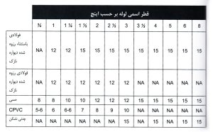
Table 4. The maximum distance between hangers (in feet) based on the type and diameter of the pipe
Types of sprinkler systems
Sprinkler systems are divided into four different types:
- More pipe systems
- dry pipe
- pre-operator
- flooding
In the Wet Pipe Sprinkler System, the sprinklers are connected to the piping network containing water, and as soon as the sprinkler is activated, the water is drained immediately.
In the Dry Pipe Sprinkler System, the sprinklers are connected to the piping network containing pressurized air, and as soon as the sprinkler is activated, the hole is emptied and the air pressure decreases, leading to the opening of the system valve and water entering the piping network. to be
In the Preaction Sprinkler System, the sprinklers are connected to the piping network containing pressurized or non-pressurized air, the command to open the system is issued by the fire alarm system installed on site.
In the deluge sprinkler system, open sprinklers are connected to the piping network, and the command to open the system valve is issued through the fire alarm system.
Many of the equipment required by the above systems are common, such as control valves, pipes, water supply, drain and test valves. Some systems may be fed from the network of hydrants, and others may use dedicated sources and pumps of the sprinkler system. In some systems, several sources may be used in order to have a higher safety factor or if the pressure and flow rate of one source is insufficient.
Wet Pipe Sprinkler System:
Pipe sprinkler systems are the simplest, most common, most reliable, and most economical system compared to other sprinkler systems, and in addition to the mentioned benefits, the cost of repairs and maintenance of this system is also much lower than other systems. Due to the pipes being full of water, as soon as the sprinkler is opened, the water is drained and the reaction time of the system is reduced. Due to the less equipment in this system, the probability of failure is also reduced and the system will be more reliable. Generally, antifreeze systems are used if the ambient temperature is below 40°F in the coldest conditions. Antifreeze Sprinkler Systems (Antifreeze Sprinkler Systems) are systems that use antifreeze solutions in the system, when the sprinkler is activated and opened, first the antifreeze solution and then the water is discharged from it. Antifreeze solutions should have a freezing temperature lower than the ambient temperature in the coldest conditions and their specific gravity should be checked. In addition, the selection of these solutions should be done in such a way that it does not conflict with the laws of health organizations.
Generally, “Shotgun Riser” or “Alarm Check Riser” is used in more systems. which consists of equipment such as one-way valve (Check Valve), pressure gauge (Pressure gauge), alarm and flow detection switches. Figure 8-2 shows an example of a gun riser, and Figure 8-3 shows a warning one-way riser in both normal and activation modes.
The steps to activate the sprinkler system are as follows:
- The system fills with water while the sprinklers are closed.
- A fire happens.
- The heat of the fire increases the temperature of the air near the roof.
- The sprinklers located in the fire area are activated.
- Water from opened sprinklers drains quickly.
- The sirens installed on the system sound after the water moves.
Dry Pipe Sprinkler System (Dry Pipe Sprinkler System):
Dry sprinkler systems are used when the air temperature is below 40°F or in situations where the ambient temperature cannot be maintained above that temperature (such as cold storage). Nitrogen or compressed air is used inside the tubes and the water is placed in a warm environment (over 40°F). Due to the water discharge time delay, we increase the “design area” (the area where the hypothetical activated sprinklers are located during a fire) by 30%. Also, the use of gridded piping method in dry systems is not allowed.
Due to the time delay of the dry pipe system (from the moment the sprinkler is activated, the valve of the system and the movement of water in the pipe and discharge from the opened sprinkler), the size of this system is limited. In general, the water discharge time from the inspection branch should be less than a specified value, except in the following two situations that NFPA makes an exception:
- If the volume of the pipes of the system is less than the limit.
- If the pipe volume is less than 750 gallons and a quick opening device is installed on the system.
The fast-opening equipment is made in two types, exhauster and accelerator, and they help the dry system valve work faster and water enters the piping network sooner.
The evacuation site can be determined by any of the following methods:
- The draining time of the dry system inspection branch (Trip Test Connection) which is the farthest sprinkler and installed on the highest floor should be less than 60 seconds.
- Using reliable software to predict the evacuation time (60 seconds from an exit or according to the time specified in Table 8-1)
- Time to drain water from the manifold according to the table
|
The maximum allowable discharge time in seconds |
The number of farthest sprinklers that are activated in the initial moments of the fire |
Risk class |
|
۶۰ |
۱ |
Low |
|
۵۰ |
۲ |
medium |
|
۴۵ |
۴ |
Much |
|
۴۰ |
۴ |
High pile warehouse |
The steps to activate the dry sprinkler system are as follows:
- The valve of the dry system is closed by the air pressure inside the pipe.
- The heat from the fire activates the fire sprinklers.
- The air comes out of the opened sprinkler and the air pressure in the system decreases.
- The system valve opens.
- Water enters the pipes.
Water is discharged from open sprinklers on the fire.
The ratio between air pressure and water pressure, which is determined by the object manufacturer, helps the valves to stay closed in a normal state. By knowing this ratio and the maximum water pressure, we can determine the air pressure required to keep the valve closed. To ensure the calculations and considering the safety factor, we will consider the calculated air pressure 20 Psi more so that the sudden increase in water pressure does not cause the valve to open.
For example, if the ratio of air pressure to water is 5:1 and the static pressure of the water source is 105 Psi, the air pressure is obtained in the following order:
۱۰۵ / ۵ = ۲۱ Psi
۲۱ ۲۰ = ۴۱ Psi Air pressure required considering 20 Psi safety factor
Increasing the air pressure in the above system to more than 41 Psi leads to an increase in the activation time of the valve because more time is required to discharge the air and reduce the pressure.
Often, in dry systems, raised sprinklers are used to prevent precipitation of water freezing sprinklers that remain in the pipe leading to the sprinkler after testing and discharge. “Return Bend” should be installed.
Preaction Sprinkler Systems:
Nitrogen is used inside the pipes of this system, which may be pressurized or non-pressurized. The water flow is stopped by the automatic control valve connected to the fire alarm system. Fire detectors are installed in all places where there are sprinklers. In case of fire, the notification system sends a signal to open the control valve and let water into the system.
The signal is not sent directly from the detector to the control valve, and the fire alarm system equipment commands the control valve of the system through the central control device (Control Panel). All kinds of detectors and fire alarms can be used in this system.
In general, pre-operator systems are implemented in three ways:
- Single Interlock: The command to open the automatic valve is issued through the fire alarm system, the size limit of this method is 1000 sprinklers in each system. After the automatic valve is opened, the system works like the other system.
- Double Interlock: The command to open the automatic valve is issued through the fire alarm system and the opening of the sprinkler. The size limit of this type of system is determined the same as the dry pipe system and the gridded piping method is not adjacent. Due to the delay in draining the water, the “design area” increases by 30%. The air pressure inside the pipes is 7 psi, and a decrease in this pressure will indicate the existence of a leak or the opening of the sprinkler.
Non-Interlock: The command to open the automatic valve is issued through the fire alarm system or sprinkler opening, the maximum number of sprinklers that can be installed in each system is 1000, this system is known as “error-free system”. because even if the fire alarm system fails, the water will drain as soon as the sprinkler is opened. The air pressure inside the pipes is 7 Psi.
In pre-acting systems, as well as dry systems, high female sprinklers are often used in order to prevent sprinkler sedimentation or freezing of water that remains in the pipe leading to the sprinkler after testing and draining, if using Female bottom sprinklers must be installed on the “return bend”.
Deluge Sprinkler System:
All the sprinklers installed in this system are of the “open sprinkler” type and the water is kept behind the automatic control valve. The electrical or pneumatic fire detection system is connected to the system valve, and fire detection equipment is installed in all places where there are sprinklers. In the event of a fire, the notification system by sending a signal causes the control valve to open, water entering the system and draining all the sprinklers. In flood systems, a significant amount of water is discharged in a short period of time.
In order to prevent the accidental discharge of water and reduce possible damages, the fire alarm system is designed in such a way that the opening of the valve is issued upon detection of at least two detectors, and the detection of fire by one detector does not lead to the opening of the valve.
Source: The book of design and calculations of sprinkler fire extinguishing systems
Sprinkler dry system / deluge sprinkler
NEWAGE
Hamyar Energy Company is the only exclusive representative of NEWAGE sprinkler (made in India) in Iran.
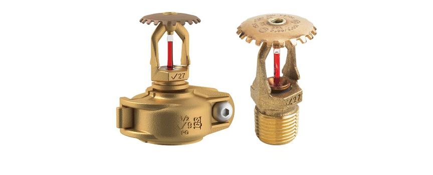
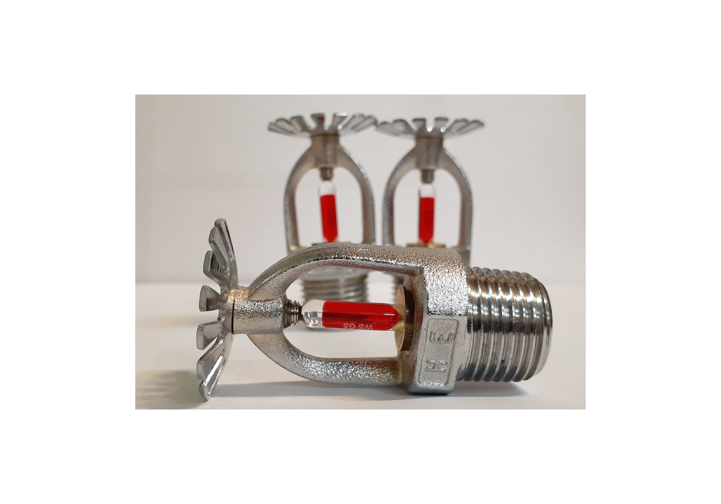
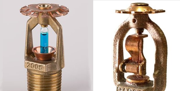
Sprinkler bulb
Sprinkler is one of the components of automatic fire extinguishing systems. The sprinkler discharges water when it detects signs of fire, such as when the temperature exceeds a certain level. The function of the sprinkler is that the sprinklers have a glass bubble containing a heat-sensitive liquid, which breaks independently in the face of fire and causes water to sprinkle on the fire and control it. Every year, more than 40 million sprinklers are installed around the world. In buildings that are protected by fire sprinklers and have standard design and maintenance, more than 99% of fires are controlled by sprinklers alone.
Statistics show that sprinkler played a very effective role in controlling fires. The more interesting thing is that in England, none of the buildings equipped with sprinkler fire extinguishing system have suffered heavy damages and death due to fire. First, we will check the components and types of sprinklers and then we will check the types of sprinkler bulbs.
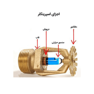
Today, the majority of sprinklers include the following:
- the frame
- Temperature sensitive glass (bulb or glass bubble)
- cap
- Flow diverter plate
- Deflector
All wet pipe sprinkler systems are closed by a fuse connection or a bulb or glass bulb containing a heat-sensitive liquid.
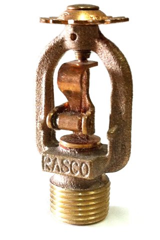
A fuse fire sprinkler head has a two-part metal element that is melted by a heat-sensitive alloy.
Holds the link, pip or cap in place. When the room temperature around the sprinkler reaches a certain temperature, the alloy melts and the metal elements separate, causing the pipe cap to fail. Then the water is released. Note that water is released only in areas where the ambient temperature reaches a certain level, so water is released only in the fire zone, which helps reduce fire damage.
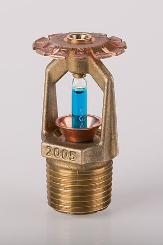
Glass bulb sprinkler heads have a small glass reservoir that holds a heat-sensitive liquid. This glass bulb keeps the pipe cap in place. When the liquid room temperature reaches a certain level, the liquid expands and causes the glass bulb to break, which causes the tube cap to pop off and release the water. Like a fuse, water is released only when the ambient temperature reaches a certain level, which helps reduce damage from a fire.
In both cases, the sprinkler heads are designed only to reach the specified room temperature. Since residential and industrial environments operate at different temperatures, it is necessary for some fire sprinkler heads to withstand higher temperatures before exploding.
An automatic sprinkler is actually a valve that is activated by heat. One of its main elements is a small glass bulb that contains a heat-sensitive liquid. They are color coded, with each color indicating the temperature at which it will explode and then release the flow of water to extinguish the fire.
All the products of Hamyar Energy Company are provided by the top manufacturers of the industry. We provide our customers with a durable product by using innovative designs and durable and high quality materials. For consultation and preparation of fire sprinkler, you can place an order through the following links:
۰۲۱-۵۷۸۵۴
۰۹۱۲۸۹۳۲۳۶۷ (call during business hours)
You, dear customer, from now on you will be able to order Hamiyar Energy fire extinguishing equipment online through the Hyperfire online store, so that you can have these products in your apartment or business place in the shortest possible time and at the most reasonable price. Use it yourself and ensure your safety and those around you. Click on the following links to buy Hamyar Energy fire extinguishing equipment: